Overview
| * | Premium replacement cartridges for standard size RO/DI systems |
| * | Remove harmful substances and purify tap water for aquarium use |
| * | Replace used cartridges to ensure best performance from your RO unit |
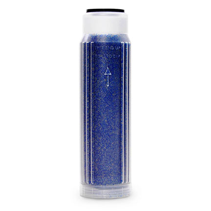
Mixed Bed Resin Cartridge (mfg# 330091)
Resin filter used in a reverse osmosis and deionization units to remove total dissolved solids (TDS). Cation and Anion resins (H+ and OH-) remove remaining TDS from RO membrane-filtered water for ultra pure water. Top gasket on cartridge allows secure fit in RO units while cartridge-housing shape lends itself to efficient water-to-resin contact. 10" standard size cartridge.
Deluxe Unit Installation (60 gpd and 100 gpd units)
Tools required for installation:
Three top-loading canisters are incorporated into the reverse osmosis filter housing. The cartridges are to be installed and replaced by removing the blue canister caps on the top of the RO unit. The canister lids should be removed by hand or with the supplied Canister Cap Wrench.
Note: Unlike traditional RO units, the easy access top-loading design of this AquaticLife RO unit positions the plumbing below the cartridges. For this reason, the Mixed Bed Resin Cartridge must be placed with the gasket side down. Water will flow through the cartridge from the top to bottom.
Tip: Use the Canister Cap Wrench to ensure a tight seal and prevent leaks.
Mounting
Wall Mount (suggested)
Using the supplied bracket and hardware, the RO unit can be mounted to a wall or flat surface.
- Affix the included template to the surface to be mounted with non-marring tape.
- Drive screws through the template and into the surface to be mounted.
- Remove the screws and template from the surface.
- Align the Mounting Plate with the two holes and drive screws until tight.
- Align the RO Housing with the Mounting Bracket and slide into place.
Tip: Use wall anchors when mounting the RO Unit to drywall. The RO Unit can weigh as much as 30 pounds when in operation.
Free Standing
The RO unit can also be used as a free-standing portable unit. In this application, it is not necessary to mount the RO unit to the wall. The RO unit is equipped with white, non-marring plastic feet to allow placement on flat, level surfaces.
Membrane Placement
- Detach the Front Cover by removing the four screws on the back side of the RO unit. TIP: A minimum 5" length #2 Phillips screwdriver is recommended.
- After removing the Front Cover, remove the yellow supply water line attached to the Membrane Housing. Remove the blue clip that secures the tubing to the connecting elbow.
- After the clip is removed, push the protruding connection from the elbow toward the elbow to release the yellow tubing from the connection.
- After the yellow tubing is detached, remove the Membrane Housing Lid. Tip: Use the supplied wrench to remove the Membrane Housing Lid.
- Remove the Membrane from the packaging and remove the protective caps before inserting into the Housing.
- Insert the Membrane into the Membrane Housing. Note: The Membrane MUST be placed into the housing with the double o-ring end first. The black ring around the other end will be inserted into the housing last.
- After inserting the Membrane into the Housing, verify that the Membrane is properly installed. The top plug of the Membrane should be flush or even with the top of the Membrane Housing.
- Replace the Membrane Lid and tighten with the supplied wrench. Reattach the yellow tubing and replace the blue clip to secure the tubing to the Membrane Housing. Proceed to the tubing installation process prior to replacing the cover back onto the unit.
Tubing Attachment
The right side of the RO unit will have four color-coded connections: Flush Line (Red), Waste Line (Red), Supply Line (Yellow) and Filtered Line (Blue). Note: Before attaching the tubing, remove the blue clips and protective plugs from the housing attachments.
Flush Connection:
This RO unit includes a manual Flush Valve for cleaning the Membrane. There are three small pieces of red tubing included with the RO.
- Insert one piece of red 10 cm tubing into the FLUSH connection on the RO unit.
- Attach the supplied Flush Valve to the other end of the red tubing.
- Attach the remaining piece of 10 cm red tubing into the other end of the valve.
Waste Connection:
- Insert the red 20 cm tubing into the Waste connection on the RO unit.
- There are now two sections of red tubing attached to the side of the RO unit - one with a valve in the middle. Next attach both red tubing ends to the supplied T.
- Attach the piece of red 2.7 m tubing to the open end of the T. This single red tube will discharge the waste water from the unit.
Supply Connection:
- Insert the yellow 3 m tubing into the Supply connection on the RO unit.
- The RO unit includes an attachment to adapt to a standard threaded utility sink or garden hose. With the faucet connection installed, insert the other end of the yellow 3 m tubing into the adaptor.
Filtered Connection:
- Insert the blue 3 m tubing into the blue Filtered connection on the RO unit.
- Attach the supply shut-off valve to the other end of the blue tubing.
Operation
Water Supply
With all tubing connections in place, turn on the supply water to the RO unit. Check to ensure that all connections are secure and there are no leaks. If all connections are secure and watertight, replace the RO unit's cover and replace the four screws that were removed. Warning: When using a new Membrane for the first time, DO NOT use the first 30 gallons of filtered water produced from the RO unit for aquariums. The Membrane includes a preservative that is removed during initial water contact.
Flush Valve
Flushing the Membrane is critical to obtaining peak performance from the RO unit. Flushing clears debris buildup on the membrane. The Deluxe RO unit includes a valve that is attached to the outside and is labeled, FLUSH (red). To flush the Membrane, open the valve for 30 seconds when the RO unit is first supplied with water. This valve allows the water to bypass the flow restrictor located inside the RO unit housing. After 30 seconds, turn the valve off. Water is now forced to pass through the flow restrictor and pressure will build against the membrane and filtered water production will resume.
Water Storage
Reverse Osmosis filtered water can be stored in covered or sealed containers for future use.
Tip: Store RO filtered water in a clean plastic barrel with lid for easy mixing of saltwater for marine aquaria.
Cartridge Replacement
- Micron Cartridge: Replace the Micron Cartridge every six months or 3,000 gallons, whichever comes first. As the cartridge fills with particulate material, it will restrict water flow and reduce the overall performance of the RO unit.
- Carbon Block Cartridge: Replace the Micron Cartridge every six months or 3,000 gallons, whichever comes first. As the cartridge fills with particulate material, it will restrict water flow and reduce the overall performance of the RO unit.
- Mixed Bed Resin Cartridge: The Mixed Bed Resin Cartridge should be replaced when the Total Dissolved Solids (TDS) level of the filtered water is above 3% of the incoming source water TDS level. This level can be calculated by dividing the TDS level of the filtered water, by the TDS level of the source water. This value will show the percentage of TDS in the filtered water.
- Membrane: The Membrane should be replaced every two years or when an increased TDS level is found even after a new Mixed Bed Resin Cartridge is installed.
100 gpd Power Unit Installation
Tools required for installation:
Cartridge Placement
Refer to the Deluxe Unit section for step-by-step instructions.
Mounting
Refer to the Deluxe Unit section for step-by-step instructions.
Membrane Placement
Refer to the Deluxe Unit section for step-by-step instructions.
Tubing Attachment
The right side of the 100 gpd Power RO unit will have three color-coded connections. Waste Line (Red), Supply Line (Yellow) and Filtered Line (Blue). Note: Before attaching the tubing, remove the blue clips and protective plugs from the housing attachments.
Supply Connection:
- Insert the yellow 3 m tubing into the SUPPLY connection on the RO unit.
- The RO unit includes an attachment to adapt to a standard threaded utility sink or garden hose. With the faucet connection installed, insert the other end of the yellow 3 m tubing into the adaptor.
Filtered Connection:
- Insert the blue 15 m tubing into the blue Filtered connection on the RO unit.
- Attach the supply shut-off valve to the other end of the blue tubing.
Operation
Water Supply
With all tubing connections in place, turn on the supply water to the RO unit. Check to ensure that all connections are secure and there are no leaks. If all connections are secure and watertight, replace the RO unit's cover and replace the four screws that were removed. Warning: When using a new Membrane for the first time, DO NOT use the first 30 gallons of filtered water produced from the RO unit for aquariums. The Membrane includes a preservative that is removed during initial water contact.
Flush Valve (automatic)
Flushing the Membrane is critical to obtaining peak performance from the RO unit. Flushing clears debris buildup on the Membrane. The Power RO unit includes an internal automatic valve that flushes the Membrane for 30-45 seconds every time the unit is activated. The internal valve allows water to bypass the flow restrictor located inside the RO unit housing. After 30-45 seconds, the valve will force the water to pass through the flow restrictor and build pressure against the Membrane. Filtered water production will then resume.
Low Pressure Switch
The Low Pressure Switch will disconnect power from the RO unit if the source water pressure is less than 4.35 PSI. This will prolong the life of the Pressure Pump.
High Pressure Switch
The High Pressure Switch will disconnect power from the RO unit if the Filtered water supply line pressure is greater than 43.5 PSI. Many RO unit installations connect to storage containers that use float valves or pressure canisters that create pressure on the Filtered water line. When the containers are full, a back pressure on the Filtered water line is created. The AquaticLife Power RO unit will disconnect power to the Pressure Pump and prevent water flow to the Membrane. Note: The water pressure supplied to the High Pressure Switch must be constant. If the pressure fluctuates, the Switch may NOT shut the system down. It is recommended that a Positive Valve be used with the Powered RO unit.
Water Spill Sensor and Alarm
A Water Spill Sensor is located inside the RO unit housing at the base. If water contacts the sensor, the computer will disconnect power to the Pressure Pump, close a valve for the incoming water supply, sound an audible alarm and the LED display will begin to flash.
Pressure Pump
The Pressure Pump increases incoming water pressure to 100 PSI. This higher pressure increases the effectiveness of the RO unit and reduces waste water output. The Pressure Pump is low voltage and is powered by the included transformer.
Automatic Shut-Off Valve
An Automatic Shut-off Valve is included with the Power RO unit to eliminate water waste and possible leak-involved problems. The Shut-off Valve will activate if the Low Pressure Switch, High Pressure Switch or Spill Sensor is activated. The computer controlled valve will stop the water supply from reaching the RO unit.
Computer Control
The Powered RO unit includes a Computer that controls the operation of the RO unit. The display will indicate several operating modes.
Reverse Osmosis filtered water can be stored in covered or sealed containers for future use. Tip: Store RO filtered water storage water in a clean plastic barrel with lid for easy mixing of saltwater for marine aquaria.


